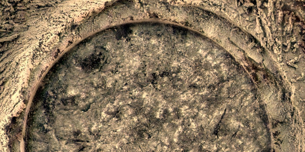
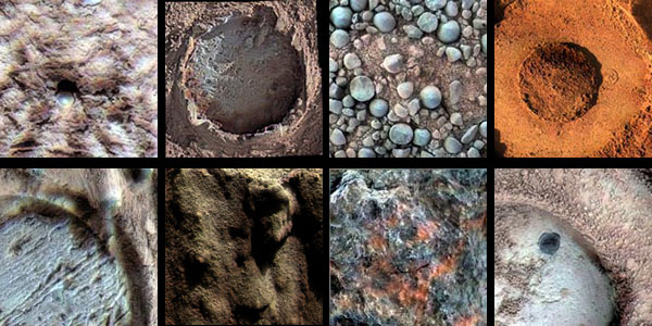
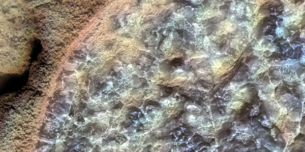
A single MI image or an Microscopic Imager mosaic can be merged with Pancam color images. The two products must be coregistered first, and then added together to produce colorized images in which the intensity comes from the MI and color (hue/saturation) comes from the Pancam images. This method of colorizing data may not yield a satisfactory product if the solar illumination is from a different direction in the Pancam relative to the MI images, or if the images are partly shadowed. It can be difficult to find where the MI overlaps the Pancam due to the scale difference (roughly a factor of 20) and differences in illumination, especially for soil targets.
Microscopic Imager / Pancam Color Merge
If a single MI image is to be merged with Pancam color, the best-focused MI image in a stack is selected. If an MI mosaic is to be merged, position information is taken from the MI image whose camera orientation was used to create the target definition file and to project all the MI images to the same plane. The Pancam color images that overlap the MI scene are selected, and radiometrically calibrated (I/F) versions are copied from JPL. We typically use Pancam images taken through filters L2 (753 nm), L5 (535 nm), and L7 (432 nm) or L4 (601 nm), L5 (535 nm), and L6 (482 nm) [Bell et al. 2003].
Level 2 files (orthographic projection) of the MI and Pancam data that have the same map scale, x-range, and y-range are then created. The default map scale used to create the orthographic projection is 0.00003 meter/pixel for all the images. This process calculates minimum and maximum x-range and y-range values to create a border around the MI image without cutting off valid data.
If an MI mosaic created in SOCET Set is to be merged with Pancam color data, the orthorectified MI images and orthomosaics are saved as TIFF images with no label information. The TIFF files are converted to ISIS and the image label information is recovered as follows: First, a sufficient number of pixels must be added around the MI Level 2 image that was used as the in-focus plane. This is done so the SOCET mosaic can be projected into the Level 2 space of the single MI frame. Next, the MI Level 2 image is copied to a new file, and all the valid pixels are set to null. The single Level 2 image and the MI mosaic are then displayed to find where the MI mosaic overlaps the Level 2 image and to make sure the scale is the same for both images. The offset between the two images is calculated and used to mosaic the MI mosaic into the nulled Level 2 file. If the registration is poor, the process is repeated.
To merge MI mosaics with a Pancam image, label information for the mosaic is created by using the plane defined by the MI image that was used to define the in-focus plane. A blank level 2 (orthographic projection) ISIS image is created that is larger than the MI mosaic image. The MI mosaic is registered to the level 2 ISIS image and mosaicked onto the orthographic image space, which creates an MI image with label information. The area of valid data is extracted. The Pancam image is projected into the same orthographic projection, the Pancam orthographic images are coregistered to the new MI level 2 image, and if any misregistration remains, then match points are picked to warp the Pancam image to the MI level 2 image. This step requires the analyst to interactively measure control points that identify the line and sample location of a number of features on both images. The input (Pancam) and output (MI) line and sample values are entered into a text file that is then read by the warping program. The MI Level 2 and the warped Pancam image are displayed to evaluate the registration. If the features do not align well, more control points are added in the areas with the most offset, and the warping program is run again. When an acceptable registration is achieved, the other two Pancam images are warped using the same input file. After all the images are coregistered, the MI and the Pancam images are merged creating a new set of red, green, and blue filter images. The tones for the MI images are matched to the Pancam data so that the color information is retained.
When the registered MI and Pancam images are generated, a script is run that creates the merged MI and Pancam color files. The output file names follow the MER naming convention for processed data products [Alexander et al., 2003]. The keywords are extracted from the labels, and formed into a filename by concatenating the keywords into a string. A text file containing information about the input files is also created following the same naming convention, but with a “.txt” rather than “.cub” extension. The final step is to generate JPEG and TIFF files that resemble the natural color of Mars. When an acceptable product has been created, the stretch pair information is added to the accompanying text file for the MI/Pancam color merge.
References
- Alexander, D., H. Mortensen, and R. Deen (2003), Mars Exploration Rover Project Software Interface Specification (SIS) Camera Experiment Data Record (EDR) and Reduced Data Record (RDR) Operations Data Products, JPL Document D-22846, Jet Propul. Lab., Pasadena, Calif.
- Bell, J. F. III and 24 others, The Mars Exploration Rover Athena Panoramic Camera (Pancam) Investigation, J. Geophys. Res., 108, 8067, doi:10.1029/2003JE00207, 2003.