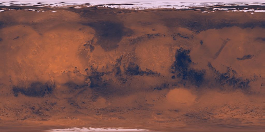
Mars Viking Global Color Mosaic 925m
- Primary Authors
- USGS Astrogeology Science Center
- Originators
- Planetary Data System
- Publisher
- USGS Astrogeology Science Center
- Abstract
- Product Information: About 1000 Viking Orbiter red- and violet-filter images have been processed to provide global color coverage of Mars at a scale of 925 meters per pixel (m). Individual image frames acquired during a single spacecraft revolution ("rev") were first processed through radiometric calibration, cosmetic cleanup, geometric control, reprojection, and mosaicking. We have produced a total of 57 "single-rev" mosaics. Phase angles range from 13 to 85 degrees. All of the mosaics are geometrically tied to the Mars Digital Image Model (MDIM), a black-and-white base map with a scale of 231 meter per pixel (m). In producing a global mosaic from Viking images with useful color and albedo information for the surface, the largest challenge has been the photometric normalization, including removal of atmospheric effects. First, we selected a subset of single-rev mosaics that provide the best global coverage (the least atmospheric obscuration and seasonal frost). A Minnaert photometric normalization was applied to normalize the variations in illumination and viewing angles. Image data acquired at illumination or emission angles larger than 77 degrees were trimmed off, as these data are strongly affected by atmospheric scattering. A model image of condensate haze was created from the violet images, consisting of 60% of the violet-filter reflectance greater than 0.05, smoothed over 20-km scales. The haze model was then subtracted from both the violet- and red-filter images. The residual polar caps were excluded from haze removal. This procedure is "conservative" in the sense that it errs on the side of under-correcting for the haze. Finally, these normalized mosaics were combined into global mosaics. Global coverage is about 98% complete in the red-filter mosaic and 95% complete in the violet-filter mosaic. A green-filter image was synthesized from an average of the red- and violet-filter data to complete a three-color set. Mission and Instrument Information: NASA's Viking Mission to Mars was composed of two spacecraft, Viking 1 and Viking 2, each consisting of an orbiter and a lander. The primary mission objectives were to obtain high resolution images of the Martian surface, characterize the structure and composition of the atmosphere and surface, and search for evidence of life. Viking 1 was launched on August 20, 1975 and arrived at Mars on June 19, 1976. The first month of orbit was devoted to imaging the surface to find appropriate landing sites for the Viking Landers. On July 20, 1976 the Viking 1 Lander separated from the Orbiter and touched down at Chryse Planitia (22.27° N, 312.05° E, planetocentric). Viking 2 was launched September 9, 1975 and entered Mars orbit on August 7, 1976. The Viking 2 Lander touched down at Utopia Planitia (47.64° N, 134.29° E, planetocentric) on September 3, 1976. The Orbiters imaged the entire surface of Mars at a resolution of 150 to 300 meters, and selected areas at 8 meters. The lowest periapsis altitude for both Orbiters was 300 km. The Viking 2 Orbiter was powered down on July 25, 1978 after 706 orbits, and the Viking 1 Orbiter on August 17, 1980, after over 1400 orbits. The Viking Landers transmitted images of the surface, took surface samples and analyzed them for composition and signs of life, studied atmospheric composition and meteorology, and deployed seismometers. The Viking 2 Lander ended communications on April 11, 1980, and the Viking 1 Lander on November 13, 1982, after transmitting over 1400 images of the two sites (Williams, 2018). References: Batson, R. M., & Eliason, E. M. (1991). Digital Maps of Mars. Photogrammetric Engineering & Remote Sensing, 61(12), 1499â1507.https://www.asprs.org/wp-content/uploads/pers/1995journal/dec/1995_dec_1499-1507.pdf Eric Eliason, Raymond Batson, Anthony Manley, Mars Mosaicked Digital Image Model (MDIM) and Digital Terrain Model (DTM), "Mission to Mars", USA_NASA_PDS_VO_2001-2007, "VO1/VO2-M-VIS-5-DIM-V1.0", NASA Planetary Data System, 2001. http://pdsimage.wr.usgs.gov/Missions/Viking_Orbiter/vo_2007 Kirk, R. L., Archinal, B. A., Lee, E. M., Davies, M. E., Colvin, T. R., & Duxbury, T. C. (2001). Global image mosaics of Mars: Assessment of geodetic accuracy. Paper presented at the 32nd Lunar Planetary Science Conference, Lunar Planetary Institute, Houston, TX. https://www.lpi.usra.edu/meetings/lpsc2003/pdf/1485.pdf Williams, D. R. (2018). Viking Mission to Mars. https://nssdc.gsfc.nasa.gov/planetary/viking.html Wu, S. S. C., & Doyle, F. J. (1990). Topographic mapping. In Greeley, R. & Batson, R. M., (Eds.), Planetary Mapping (pp. 169-207). New York, Cambridge University Press. ISBN 0-521-30774-0 Wu, S. S. C., & Schafer, F. J. (1984). Mars control network. In Technical papers of the 50th annual meeting of the American Society of Photogrammetry (Vol. 2, pp. 456-463). Washington, DC: American Congress on Surveying and Mapping. ISBN 0937294713
- Purpose
- This Mars color mosaic incorporated roughly 1000 Viking Orbiter images and provides gap-free coverage of the Martian surface.
Contact and Distribution
- Format
- Global Mosaic, Remote-sensing Data
- Access Constraints
- public domain
- Access Scope
- PDS
- Use Constraints
- None
- Edition
- MDIM 1
- Supplemental Information
- http://pdsimage.wr.usgs.gov/Missions/Viking_Orbiter/vo_2007/
- Native Data Set Environment
- ISIS v3
- Astrogeology Theme
- Geomorphology, Image Processing, Remote Sensing
- Mission Names
- Viking
- Instrument Names
- VIS
- Online Package Link
- https://astrogeology.usgs.gov/search/map/mars_viking_global_color_mosaic_925m
- External File Size
- 764 MB
- Online File Link
- https://planetarymaps.usgs.gov/mosaic/Mars_Viking_ClrMosaic_global_925m.tif
- Contact Address
- 2255 N. Gemini Drive
- Contact City
- Flagstaff
- Contact State
- AZ
- Contact Postal Code
- 86001
- Contact Email
- astroweb@usgs.gov
- Currentness Reference
- Publication date
- Progress
- Complete
- Update Frequency
- None planned
- Logical Consistency
- As noted in the process description, images in the mosaic were obtained under a wide range of illumination conditions and were processed by a simple scheme intended to reduce but not eliminate differences in appearance of topographic features. Comparison of such features in different parts of the mosaic should therefore be considered only qualitative. The majority of the source images have resolutions in the range of 200 to 300 m/pixel, but images with resolutions as poor as 1000 m/pixel were used to fill gaps in a few areas. The accuracy of the original MDIM could not be evaluated at the time of its production, because of the lack of a suitable reference data set of higher accuracy. The precision of the control network on which the mosaic was based was estimated at 20 pixels (5 km) root-mean-square (RMS) (Batson and Eliason, 1991) Subsequent control networks and mosaics were later produced from the same images but with a number of improvements, primarily 1) use of Mars Orbiter Laser Altimeter (MOLA)-derived elevations (~10 m vertical accuracy) to constrain all network points; 2) use of MOLA-derived horizontal coordinates to constrain a globally distributed set of points; and 3) use of the MOLA elevations to orthorectify the images before mosaicking. Comparison of the coordinates for the center point of each image in MDIM 1.0 and in the later, MOLA-controlled product indicated mean differences of 0.16 km in easting and -1.01 km in northing, with RMS differences of 3.15 and 4.33 km. The contribution of errors in the MOLA coordinates (<0.1 km horizontal accuracy) and the later MDIM tied to it (~0.3 RMS accuracy relative to MOLA) contribute negligibly to this result. Note that some confusion exists in the literature over the systematic error of MDIM 1.0 in longitude. The mosaic was tied to an erroneous identification of the Viking 1 landing site approximately 0.2° from the true location, which would correspond to an error of ~12 km in easting, but this error was partly corrected by adjustment of the W0 rotational parameter to place the crater Airy 0 at zero longitude. Furthermore, comparisons between MDIM 1.0 and an intermediate solution (MDIM 2.0) partially tied to MOLA indicated a 6.7 km (0.11°) mean difference in longitude. This difference was attributed primarily to errors in MDIM 1.0 but in fact was primarily an error in MDIM 2.0, with MOLA and the final MDIM 2.1 control solution coincidentally quite close to the original product.
- Completeness Report
- This Mars mosaicked digital image model (MDIM) incorporated roughly 4600 Viking Orbiter images and provides gap-free coverage of the Marian surface.
- Process Description
- Cartographic experts at the USGS Astrogeology Science Center in Flagstaff, Ariz., created the MDIM mosaic. The images underwent noise removal, radiometric, geometric and photometric correction, reseau removal, and tone matching. The ground control points were established based on a low resolution mosaic produced at USGS under the direction of Sherman Wu. In addition to the ground points, a network of tie points was collected between all identifiable overlapping images, making sure that all four sides were tack to other images. Once the camera pointing was updated for a set of images, the updated camera pointing information was saved and stored so for later access if necessary. The images with the corrected geometry were projected to a sinusoidal equal area projection and mosaicked together. The tones were matched using a highpass and lowpass filtering technique to simulate a photometric correction. The images used in MDIM 1.0 were obtained over wide ranges of incidence and phase angles and atmospheric haze. As a result, it was not possible to preserve the radiometric integrity of the observations and simultaneously produce a uniform representation of the Martian surface. Instead, a simple radiometric-photometric processing approach was used that yielded a mosaic with reasonably uniform brightness and contrast. In particular, the differences in the contrast of topographic features of similar slope that were imaged at different incidence angles have been reduced. This processing consisted of highpass spatial filtering to suppress regional-scale albedo variations and gradients in illumination, followed by normalization of the slope-dependence of surface reflectance, based on a Lambert reflectance model. Because the processing was carried out on images with 8-bit integer pixel values, additional radiometric distortions such as contouring were introduced in areas of low original contrast.
- Source Title
- Viking Online Data Volumes
- Source Online Linkage
- {https://pds-imaging.jpl.nasa.gov/volumes/viking.html#vkoEDR,https://pds-imaging.jpl.nasa.gov/portal/vikingo_mission.html}
- PDS Status
- PDS 3 Like
- Attribute Accuracy Report
- Accurate to Control Net
- Horizontal Positional Accuracy Report
- Accurate to Control Net
Geospatial Information
- Target
- Mars
- System
- Mars
- Minimum Latitude
- -90
- Maximum Latitude
- 90
- Minimum Longitude
- -180
- Maximum Longitude
- 180
- Direct Spatial Reference Method
- Raster
- Object Type
- Grid Cell
- Raster Row Count (lines)
- 11530
- Raster Column Count (samples)
- 23059
- Bit Type (8, 16, 32)
- 8
- Quad Name
- Radius A
- 3396190
- Radius C
- 3376200
- Bands
- 3
- Pixel Resolution (meters/pixel)
- 925.406
- Scale (pixels/degree)
- 64.05264
- Map Projection Name
- Simple Cylindrical
- Latitude Type
- Planetocentric
- Longitude Direction
- Positive East
- Longitude Domain
- -180 to 180


