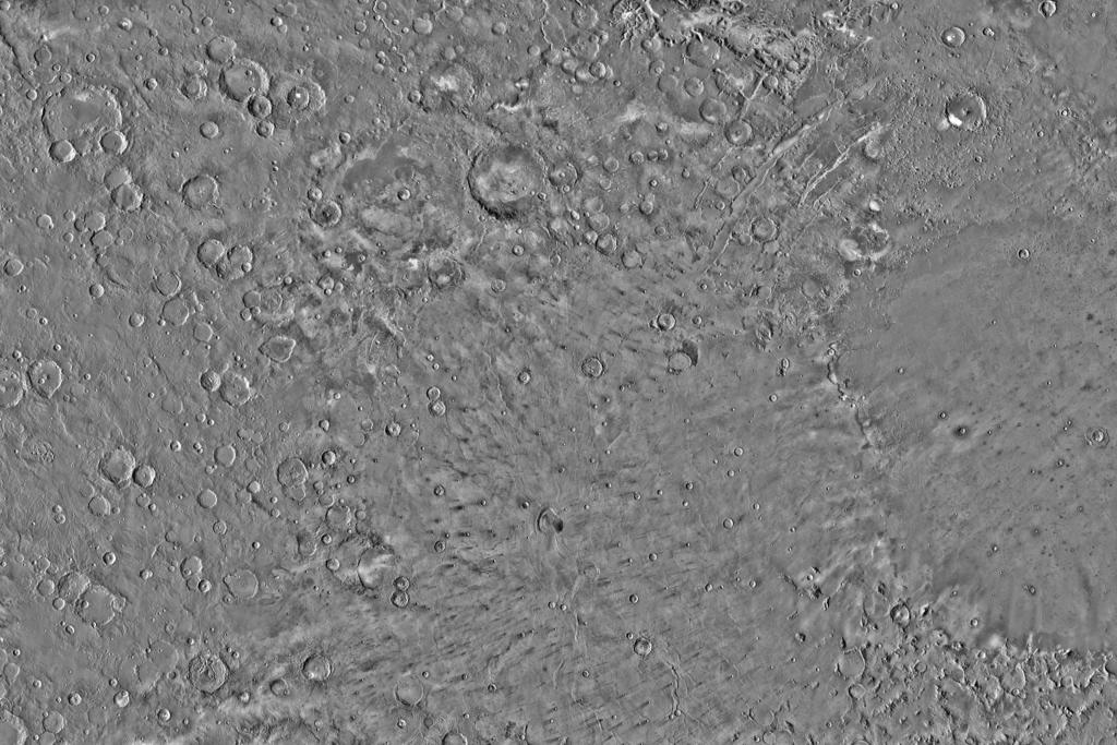
Mars THEMIS Day IR Controlled Mosaic Syrtis Major 00N 45E 100 mpp
- Primary Authors
- Robin Fergason
- Originators
- USGS Astrogeology Science Center
- Publisher
- USGS Astrogeology Science Center
- Abstract
- This product is an infrared image mosaic generated using Thermal Emission Imaging System (THEMIS) images from the 2001 Mars Odyssey orbiter mission. The mosaic is generated at the full resolution of the THEMIS infrared dataset, which is approximately 100 meters/pixel. The mosaic was registered horizontally to an improved Viking MDIM network that was develop by the USGS Astrogeology cartography group.
- Purpose
- This work is funded by the Planetary Geology and Geophysics (PGG) Cartography program to improve the registration of the THEMIS infrared dataset. These controlled mosaics and improved image pointing knowledge will positively impact both the work performed by the Astrogeology cartography group and a broad range of disciplines within the larger science community. Controlled THEMIS mosaics will benefit geologic mapping efforts (superior basemap), landed science operations (site characterization and traverse planning), and orbital observation planning (precision targeting). The control networks that result constitute a (potentially global) framework for the precision cartographic control of existing and future higher spatial resolution data products (e.g. CTX), and will allow the registration of historical data sets to be improved. In addition, the preliminary smithed kernels will be very valuable to scientists and allow them to perform quantitative analyses with THEMIS images using improved pointing knowledge as well as the precision and accuracy of that knowledge.
Contact and Distribution
- Format
- Raster Data, Regional Mosaic
- Access Constraints
- Public domain
- Access Scope
- Use Constraints
- Please cite authors
- Edition
- 1
- Supplemental Information
- http://link.springer.com/article/10.1023/B:SPAC.0000021008.16305.94, http://www.lpi.usra.edu/meetings/lpsc2013/pdf/1642.pdf
- Native Data Set Environment
- ISIS v3
- Astrogeology Theme
- Cartography
- Mission Names
- Mars Odyssey
- Instrument Names
- IR, MOLA, THEMIS
- Online Package Link
- https://astrogeology.usgs.gov/search/map/mars_themis_day_ir_controlled_mosaic_syrtis_major_00n_45e_100_mpp
- External File Size
- 453 MB
- Online File Link
- https://planetarymaps.usgs.gov/mosaic/Mars/THEMIS_controlled_mosaics/SyrtisMajor_DayIR_31July2014/THEMIS_DayIR_ControlledMosaic_SyrtisMajor_00N45E_100mpp.tif
- Contact Address
- 2255 N. Gemini Drive
- Contact City
- Flagstaff
- Contact State
- AZ
- Contact Postal Code
- 86001
- Contact Email
- astroweb@usgs.gov
- Currentness Reference
- Ground condition
- Progress
- Complete
- Update Frequency
- None planned
- Completeness Report
- When generating the control network, Thermal Emission Imaging System (THEMIS) infrared images were constrained by the latitude and longitude of the bounding coordinates of the region. We also constrained the following parameters: Mars Odyssey orbits 816 to 30150, emission angle 0 to 30, number of lines in the image of 300 to 50, 000, sampling of 1 to 2, and percent of image missing 0 to 40. No filtering is performed to remove images where there is redundant coverage; all available images are included. Images were deleted from the control network (and therefore are not included in the mosaic) if poor image quality prevented the ability to resolve features and allow the image to be controlled. Images with a spatial summing of 2 were not compatible with all post-processing steps. These images were included in the control network (kernels), but not in the mosaic. Areas within the mosaic that have gaps either have no THEMIS infrared coverage at the time the mosaic was created or poor quality images were removed.
- Process Description
- The regions follow the standard mapping format of Mars at 1:5, 000, 000 scale. Following this previously established convention allows for continuity between these mosaics and their use as base maps for planetary mappers, and is also a convention with which scientists are already familiar. The USGS Astrogeology Science Center has developed automatic sub-pixel registration and bundle adjustment software that are used to generate the THEMIS infrared control networks and are part of the ISIS software package. We utilized this software to perform automatic sub-pixel registration techniques with human oversight. We first automatically plan the placement of control points on a given set of overlapping images (seedgrid and autoseed) and automatically measure tie points in the specified area (pointreg). Given a well-known geometry, the automated registration software used to locate corresponding features in image pairs has been found to be very successful (i.e. a success rate of better than 95% in moderate to high thermal inertia regions). Using this automated software, we perform least squares bundle adjustment of control point image measurements and develop the individual, small control networks (jigsaw). We are also able to solve for the formal uncertainties of the position of each image in each control network, as well as any correlation between them, via inversion of the normal matrix. After image-to-image ties are completed, we then tie the THEMIS tiles to ground using an improved Viking Mars Digital Image Model (MDIM) network that was developed by the USGS Astrogeology cartography group (funded by PGG Cartography). To generate the improved Viking MDIM network, the original MDIM 2.1 (Archinal et al. (2003), Mars digital Image Model 2.1 control network, Lunar and Planetary Science XXXIV, Houston, TX, Abstract #1485; Archinal et al.(2004), A new Mars Digital Image Model (MDIM 2.1) control network, XXth ISPRS congress, Istanbul, Turkey) was reprocessed using HRSC level 4 data (Jaumann et al. (2007), The High-Resolution Stereo Camera (HRSC) experiment on Mars Express: Instrument aspects and experiment conduct from interplanetary cruise through the nominal mission, Planet and Space. Sci., 55, 928-952) as additional ground control. Over 1260 HRSC Digital Terrain Models (DTMs) distributed across the Martian surface were chosen to provide global coverage. Elevations of all points that did not already have MOLA derived elevations were constrained to be near the MOLA DTM. These additions allowed the accuracy of the over one thousand manual grid ties from the original MDIM 2.1 to be better estimated, and error propagation showed that 80% of the final enhanced MDIM solution tie points have horizontal accuracies better than 200 meters. The published horizontal accuracy of the MOLA gridded data (probably the most commonly used geodetic reference on Mars) is 250 meters (Neumann et al. (2001), Crossover analysis of Mars Orbiter Laser Altimeter data, J. Geophys. Res., 106, 23, 752-23, 768). However, the accuracy of the MOLA data in a particular area has not been well quantified and varies significantly with location. For example, at the equator the data may have been interpolated between MOLA tracks for multiple kilometers. The improved MDIM 2.1 network therefore has comparable, and in many cases superior, horizontal accuracy. THEMIS tiles were tied to the improved MDIM network ground points. The coordinates of these ground points were constrained to improved MDIM values, taking advantage of individually calculated point uncertainties. All of the control networks have average “jigsaw” residuals less than a single pixel, and the 3-sigma residual is also less than a single pixel. Thus, these mosaics achieve sub-pixel precision in image space. In many cases, the position of a single THEMIS image is adjusted by 5-7 pixels (equivalent to ~30 CRISM pixels, 100 CTX pixels, and 2000 HiRISE pixels), and adjustments as large as 15 or more pixels have been necessary. The accuracy of the final product (mosaics and preliminary smithed kernels) is limited by the accuracy of the coordinate system we are using for ground control. Therefore, the horizontal accuracy of the final products relative to the MOLA topographic model ranges from 150 to 275 meters, which translates to 1.5 to 2.75 pixels. Controlling the THEMIS data for these areas has significantly improved the registration of the THEMIS images. This control network will improve the registration of the THEMIS IR data set, enhance our knowledge of image placement and the location of small-scale surface features, provide for improved targeting of current and future orbital acquisition of data, and allow for improved targeting of spacecraft landings. Seamless mosaics were generated using band 9 (centered at a wavelength of 12.57 µm) data at 100 meters/pixel scale, which is the full resolution of the THEMIS infrared data set. To generate the mosaic, we first downloaded PDS-released THEMIS reduced data records (RDRs) and used the preliminary smithed kernels generated from our control network. We utilized the THEMIS mosaicking procedure developed by Arizona State University (Edwards et al. (2011), Mosaicking of global planetary image datasets: 1. Techniques and data processing for Thermal Emission Imaging System (THEMIS) multi-spectral data, J. Geophys. Res., 116, E10009, doi:10.1029/2010JE003755), which uses DaVinci software scripts to post-process images (uddw), reduce image noise (rtilt, deplaid, and destreak), and remove seams between images (blend, sstretch and a high-pass filter). The resulting mosaics are qualitative (8-bit) products.
- Source Title
- THEMIS IR
- Source Online Linkage
- http://global-data.mars.asu.edu/bin/themis.pl
- Attribute Accuracy Report
- Best Effort
- Horizontal Positional Accuracy Report
- Accurate to Control Net
Geospatial Information
- Target
- Mars
- System
- Mars
- Minimum Latitude
- 0
- Maximum Latitude
- 30
- Minimum Longitude
- 45
- Maximum Longitude
- 90
- Direct Spatial Reference Method
- Raster
- Object Type
- Grid Cell
- Raster Row Count (lines)
- 17783
- Raster Column Count (samples)
- 26674
- Bit Type (8, 16, 32)
- 8
- Quad Name
- Radius A
- 3396190
- Radius C
- 3376200
- Bands
- 1
- Pixel Resolution (meters/pixel)
- 100
- Scale (pixels/degree)
- 592.747
- Map Projection Name
- Simple Cylindrical
- Latitude Type
- Planetocentric
- Longitude Direction
- Positive East
- Longitude Domain
- 0 to 360

